 MarioandMattijs Vanhaverbeke
5d20a7ad15
MarioandMattijs Vanhaverbeke
5d20a7ad15
* Added some individual options

* Added general options

* Added show_single_cable_logical_conns and draw_default_layout

* Added ignore_cable_type to IndividualOptions

* Corrected permission, tiny improvements

* Add preselected_device_roles to IndividualOptions

* Add preselected_tags

* Updated documentation

* Update README.md

* Corrected queryset for preselected_tags

* Update README.md

* move supported_termination_types to inside the function to prevent migration issues

* removed general options

* added new migration script

---------

Co-authored-by: Mattijs Vanhaverbeke <mattijs.vanhaverbeke@ebo-enterprises.com>
161 lines
8.0 KiB
Markdown
161 lines
8.0 KiB
Markdown
# Netbox Topology Views Plugin
|
|
|
|
 
|
|
|
|
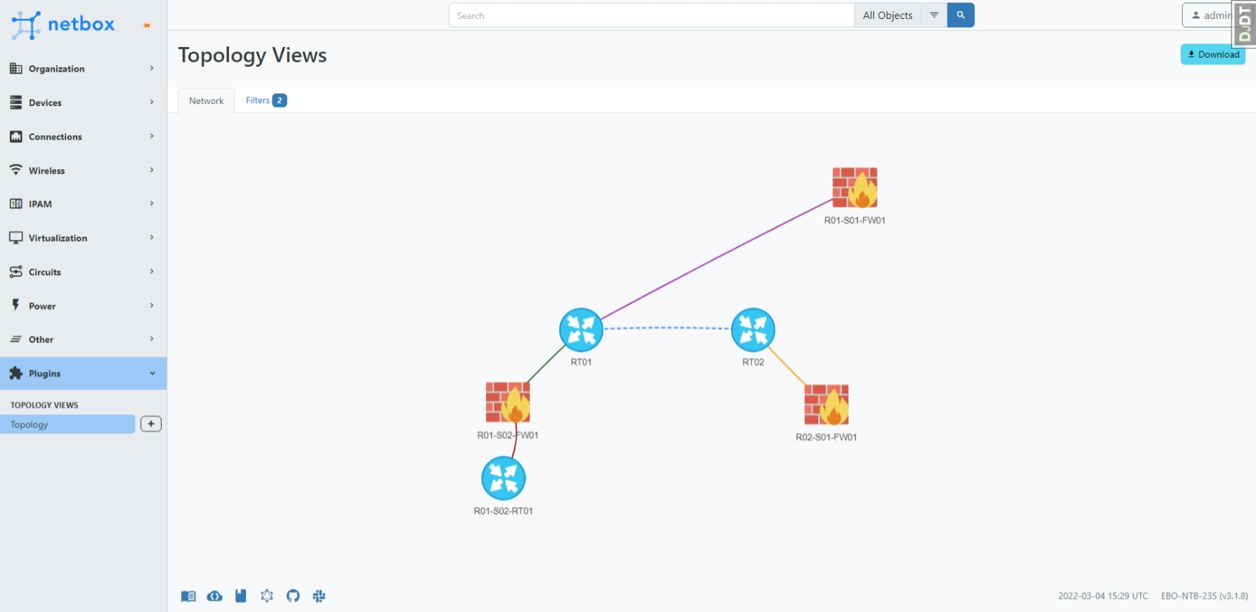
Create topology views/maps from your devices in netbox.
|
|
The connections are based on the cables you created in netbox.
|
|
Support to filter on name, site, tag and device role.
|
|
|
|
## Preview
|
|
|
|
|
|
|
|
## Install
|
|
|
|
**_NOTE:_** For docker please see: [Docker install](https://github.com/netbox-community/netbox-docker/wiki/Using-Netbox-Plugins)
|
|
|
|
The plugin is available as a Python package and can be installed with pip.
|
|
|
|
Run `pip install netbox-topology-views` in your virtual env.
|
|
|
|
To ensure NetBox Topology Views plugin is automatically re-installed during future upgrades, create a file named `local_requirements.txt` (if not already existing) in the NetBox root directory (alongside `requirements.txt`) and list the `netbox-topology-views` package:
|
|
|
|
```no-highlight
|
|
# echo netbox-topology-views >> local_requirements.txt
|
|
```
|
|
|
|
Once installed, the plugin needs to be enabled in your `configuration.py`
|
|
|
|
```python
|
|
# In your configuration.py
|
|
PLUGINS = ["netbox_topology_views"]
|
|
```
|
|
|
|
First run `source /opt/netbox/venv/bin/activate` to enter the Python virtual environment.
|
|
|
|
|
|
Then run
|
|
```bash
|
|
cd /opt/netbox/netbox
|
|
pip3 install netbox-topology-views
|
|
python3 manage.py migrate netbox_topology_views
|
|
python3 manage.py collectstatic --no-input
|
|
```
|
|
|
|
### Versions
|
|
|
|
| netbox version | netbox-topology-views version |
|
|
| -------------- | ----------------------------- |
|
|
| >= 3.4.0 | >= v3.X.X |
|
|
| >= 3.3.0 | >= v3.0.0 |
|
|
| >= 3.2.0 | >= v1.1.0 |
|
|
| >= 3.1.8 | >= v1.0.0 |
|
|
| >= 2.11.1 | >= v0.5.3 |
|
|
| >= 2.10.0 | >= v0.5.0 |
|
|
| < 2.10.0 | =< v0.4.10 |
|
|
|
|
### Custom field: coordinates
|
|
|
|
There is also support for custom fields.
|
|
|
|
If you create a custom field "coordinates" for "dcim > device" and "Circuits > circuit" with type "text" and name "coordinates" you will see the same layout every time. It is recommended to set this field to "UI visibility" "Hidden" and let the plugin manage it in the background.
|
|
|
|
The coordinates are stored as: "X;Y".
|
|
|
|
Please read the "Configure" chapter to set the `allow_coordinates_saving` option to True.
|
|
You might also set the `always_save_coordinates` option to True.
|
|
|
|
## Configure
|
|
|
|
All individual options can be assigned a default value per user directly in the plugin. The default value can be overridden on the filter page.
|
|
|
|
The remaining options must be configured in the `PLUGINS_CONFIG` section of your `netbox/configuration.py`.
|
|
|
|
Example:
|
|
```
|
|
PLUGINS_CONFIG = {
|
|
'netbox_topology_views': {
|
|
'static_image_directory': 'netbox_topology_views/img',
|
|
'allow_coordinates_saving': True,
|
|
'always_save_coordinates': True
|
|
}
|
|
}
|
|
```
|
|
|
|
| Setting | Default value | Description |
|
|
| ------------------------ | ---------------------------------------------------------------------------------------------------------------------------------------------- | ---------------------------------------------------------------------------------------------------------------------- |
|
|
| static_image_directory | netbox_topology_views/img | (str or pathlib.Path) Specifies the location that images will be loaded from by default. Must be within `STATIC_ROOT` |
|
|
| allow_coordinates_saving | False | (bool) Set to true if you use the custom coordinates fields and want to save the coordinates |
|
|
| always_save_coordinates | False | (bool) Set if you want to enable the option to save coordinates by default |
|
|
|
|
### Custom Images
|
|
|
|
To change image with associated device use the `Images` page - it allows to map a device role with an image found in the netbox static directory (defined by the plugin config `static_image_directory` which defaults to `netbox_topology_views/img`). You can also upload you own custom images to there - these images will automatically be used for a device (if it does not already have a specified image in the settings) if their name is the device role slug.
|
|
|
|
## Use
|
|
|
|
Go to the plugins tab in the navbar and click topology or go to `$NETBOX_URL/plugins/netbox_topology_views/` to view your topologies
|
|
|
|
Select your options for the topology view:
|
|
|
|

|
|
|
|
<dl>
|
|
<dt>Save Coordinates</dt>
|
|
<dd>Save the coordinates of devices in the topology view.</dd>
|
|
<dt>Show Unconnected</dt>
|
|
<dd>Show devices that have no connections or for which no connection is displayed. This option depends on other parameters like 'Show Cables' and 'Show Logical Connections'.</dd>
|
|
<dt>Show Circuit Terminations</dt>
|
|
<dd>Show connections which end at a circuit termination in the topology view. These connections are displayed as blue dashed lines.</dd>
|
|
<dt>Show Cables</dt>
|
|
<dd>Show connections between interfaces, front / rear ports, etc., that are connected with one or more cables. These connections are displayed as solid lines in the color of the cable.</dd>
|
|
<dt>Show Logical Connections</dt>
|
|
<dd>Show logical connections between interfaces (referred to as Interface Connections in NetBox) in the topology view. Where the path between
|
|
interfaces includes multiple cables (e.g., via patch panels), only the end interface connections are shown, not the
|
|
intermediate front / rear port connections, etc. This is similar to what was referred to as 'end-to-end' connections in previous versions. These connections are displayed as yellow dotted lines.</dd>
|
|
<dt>Show redundant Cable and Locigal Connection</dt>
|
|
<dd>Shows a logical connection (in addition to a cable), even if a cable is directly connected. Leaving this option disabled prevents that redundant display. This option only has an effect if 'Show Logical Connections' is activated.</dd>
|
|
<dt>Show Power Feeds</dt>
|
|
<dd>Displays connections between power outlets and power ports. These connections are displayed as solid lines in the color of the cable. This option depends on 'Show Cables'.</dd>
|
|
<dt>Show Wireless Links</dt>
|
|
<dd>Displays wireless connections. These connections are displayed as blue dotted lines.</dd>
|
|
</dl>
|
|
|
|
### Update
|
|
|
|
Run `pip install netbox-topology-views --upgrade` in your venv.
|
|
|
|
Run `python3 manage.py migrate netbox_topology_views`
|
|
|
|
Run `python3 manage.py collectstatic --no-input`
|
|
|
|
|
|
Clear you browser cache.
|
|
|
|
|
|
### Permissions
|
|
|
|
To view `/plugins/netbox_topology-views/topology` you need the following permissions:
|
|
+ dcim | device | can view device
|
|
+ dcim | site | can view site
|
|
+ extras | tag | can view tag
|
|
+ dcim | device role | can view device role
|
|
|
|
To view `/plugins/netbox_topology-views/image`:
|
|
+ dcim | site | view
|
|
+ dcim | device role | view
|
|
+ dcim | device role | add
|
|
+ dcim | device role | change
|
|
|
|
To view `/plugins/netbox_topology-views/individualoptions`:
|
|
+ netbox topology views | individualoptions | change
|
|
|
|
## Icons info
|
|
|
|
Power icons created by [Freepik - Flaticon](https://www.flaticon.com/free-icons/power).
|
|
|
|
Power icons created by [Flat Icons - Flaticon](https://www.flaticon.com/free-icons/power)
|
|
|
|
Provider icons created by [Good Ware - Flaticon](https://www.flaticon.com/free-icons/provider)
|
|
|